|
|
|
Kategorie
|
|
Informacje
|
|
Polecamy
|
|
|
 |
|
|
Dla tego produktu nie napisano jeszcze recenzji!
 ;
Schematy są ale można wysilić się i zrobić kolorowy skan i o większej rozdzielczości. Wtedy schematy płytek będą czytelniejsze. Całość super jako wartość merytoryczna. Wszystkie dane potrzebne do podłączenia różnego rodzajów urządzeń takich gramofon, CD itd.
 ;
Szybko, sprawnie i tanio. Serwis godny polecenia. Będę polecał innym
;
Ogólnie jest OK, z wyjątkiem obrazu płyty głównej, który jest miejscami mało czytelny, ale można sobie poradzić.
;
Dokładna dokumentacja, pomogła w szybkiej naprawie telewizora. Dziękuję!
;
jedyne do czego mogę mieć zastrzeżenie to jakość zdjęć zawartych w przesłanej instrukcji serwisowej ponieważ są fatalnej jakości, praktycznie nieczytelne. tak poza tym jestem zadowolony to jest to czego szukałem.
I
Section IV Paragraphs 4-7 to 4-14 4-7. DIFFERENTIAL AMPLIFIER. Differential amplifier VlO2A/B amplifies the signal from cathode follower VlOlA/B and converts it f r o m a single-ended signal to the balanced signal necessary for the main vertical amplifier. In any operating mode other than A-B, the grid of V102B is fixed a t a dc level set by cathode follower VlOlB. When a signal appears at the grid of V102A it is amplified and appears a s a signal at the plate. A t the same time a signal appears a t the cathode of V102A. Since the cathodes of the two halves of V102 a r e tied together this signal appears between the cathode and gridofVlO2B. This differential signal is also amplified and appears at the plate of V102B as a signal opposite in polarityto the signal on the plate of V102A. In the A-B mode, the signal from the ChannelAattenuator is switched toVlO2A and the signal from the channel B attenuator is switched to V102B. The operation of the differential amplifier in this mode is similar to that described above: a signal appears at the grid of V102A and is amplified; the same signal appears at the cathode, but since another signal now appears at the grid of V102B only the difference signal between channel A and channel B is amplified. Therefore, any signal which appears a t both grids with the same phase and amplitude (common mode) will not appear in the output. 4-8. With VERNIER control R123 in CALIBRATED the cathode of V102A and V102B a r e tied together. When R123 is rotated out of the CALIBRATED position resistance is inserted between the cathodes. This resistance acts a s degenerative feedback and lowers the gain of the stage, giving the desired control of the deflection sensitivity. If the two halves of the tube were identical and R l l l andR112 had exactly the same value, then R123 would have no effect on the dc balance of the differential amplifier. However, since these components are not identical, BAL. control R104 adjusts the operating point of the differential amplifier stages so that the two cathode voltages a r e equal and no current flows through R123 to change the balance of the stage and move the vertical position of the trace. A means of bringing the SENSITIVITY scales into calibration is provided by SENS. CAL. control R120. This control acts a s a voltage divider with R113 and R114, changing the operating point of V102 toward lower plate current, lowering the transconductance and the gain. In this manner the entire vertical amplifier may be brought into calibration. 4-9. OUTPUT CATHODE FOLLOWER. The output of differential amplifier V102 is connected through coupling networks R121-L103 and R122-L104 to the grids of output cathode follower V103. These networks are necessary to compensate for differences in the frequency response of the two channels due to switch and wiring capacitance. These networks a r e not used in the channel B amplifier. 4-10. To achieve control over the vertical trace position, VERTICAL POSITION control R127-128 varies the dc bias in the grid circuit of V103. This in turn varies the cathode voltage of V103, and thus the vertical position of the trace. 4- 2
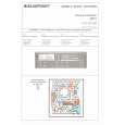
Model 162B 4-11. CONSTANT CURRENT GENERATOR. The ac signal is coupled to the output through C307 and C308, but the dc signal is reduced in level from +75 volts a t the cathode of V103A to approximately zero volts a t the output. Referring to figure 4-4, thegrid of V303A is biased by voltage divider R320-321 to -32 volts. This fixed bias, along with cathode bias resistor R318, regulates the tube a t a constant plate current. Since V303A draws constant current through R310, an increase in dc level will not change the drop across R310 and the d c signal will appear at the output unattenuated. Positive feedback from the input through R312 compensates for the voltage division by I1308 and the 1 megohm resistor in the input of the main vertical amplifier. R308 isolates the output from the capacitance of V303A. 4-12. Vert. Pos. Adj. R319 acts a s a coarse vertical position control and allows centering of the range of VERTICAL POSITION control R127-128. Potentiometer R19 adjusts the cathode voltage of V303A and thereby adjusts the dc level a t the plate of V303A, resulting in the same effect a s adjustment of R127-128.
4-13. E L E C T R O N I C S W I T C H .
4-14. The output of each channel is controlled by switching multivibrator V302, shown in figure 4-5. When V302A conducts, its plate voltage is approximately t-45 volts, forward-biasing diode CR301. The conduction of CR301 pulls the plates of V102 (and therefore the grids of V103) to approximately ~60 volts, cutting off V103. With V103 in a cutoff Zondition, no signal from channel A appears in the
SIGNAL FROM -& V102A
V103A
R
3
1
R 3 04 8
~
~
OUTPUT
ITRVERT3 I R3
8
POS. ADJ.
R317
SO-S-1958
To
-v
Figure 4-4. Constant Current Generator 01558-1
|
|
|
> |
|